How to Use 3D Print Infill Settings – Increase Strength, Save Filament
At 3DSourced we’ve covered everything 3D printing and 3D since 2017. Our team has interviewed the most innovative 3D printing experts, tested and reviewed more than 20 of the most popular 3D printers and 3D scanners to give our honest recommendations, and written more than 500 3D printing guides over the last 5 years.
What Does Infill Mean in 3D printing?
Most FDM objects are not printed as solid objects, because that would use a ton of filament and take quite a long time to print.
On the other hand, a totally hollow print would be impractical, as it would easily fail under the stress of normal usage.
Infill 3D printing is a compromise between these two positions.
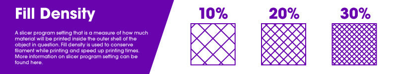
Infill density is the amount of filament printed inside the object, and directly relates to the strength, weight, and printing duration of your print.
In this article, I’ll explain the methods I use to choose the right infill percentage and patterns for my projects to maximize strength and cost savings.
We’ll then cover any troubleshooting with infill related problems and how to compensate when using low or no infill.
We also have an article on the best infill settings for every project and filament type.
Need to Know: Infill in 3D Printing
How to Choose Infill Percentage
Table Of Contents
- What Does Infill Mean in 3D printing?
- Need to Know: Infill in 3D Printing
- How to Choose Infill Percentage in 3D Printing
- Basic Object Sections
- Infill Shapes
- Cura Infill Overlap
- Using Shell Thickness to Reduce Infill Percentage
- 3D Printer Infill Percentage and Overall Object Strength
- Infill Problems
- Adaptive Makerbot Infill Patterns
- Summary
How to Choose Infill Percentage in 3D Printing
3D Printer infill patterns, or the internal structure of an object, are a necessary part of printing some 3D objects, especially those that require a measure of strength or sturdiness. That being said, infill is also something of a pain.
If you want your print job to succeed, you’re likely to have to use a solid shell with at least a modicum of infill. However, the more infill you use, the higher the cost and the print time of the object becomes. It’s worth taking a moment to decide your optimum 3D printing infill percentage.
In this article, we’re going to take a close look at the process of infilling. We’ll examine the pros and cons of 3D printing infill types and density.
We’ll look at how to balance the amount of infill against the object’s intended use, to optimize strength while keeping costs and printing time to a minimum.
Finally, we’ll look at how some of the cutting-edge slicer software that is presently hitting the market is changing the concept of infill. So keep reading to learn the best infill pattern for your prints.
Basic Object Sections
In general, a routine FDM object consists of four sections. The design criteria of each of these sections can be individually altered so that an optimized design is achieved. The sections are:
- Shell – The outside walls of an object, typically built up vertically along the z-axis.
- Bottom layers – A part of the shell comprised of an outside wall of an object, initially attached to the build plate.
- Top layers – A part of the shell comprised of an outside wall of an object, facing upwards. Usually the last part of an object to print.
- Infill – The material that comprises the interior of the object between the shell or walls.
Infill Shapes
There are several infill shapes typically available in most slicer programs. For example, Cura’s infill patterns include Honeycomb and Triangles among others.
Which one is right for you depends on what type of object you’re planning on creating and the 3D printing infill strength you require.
- Rectangular – This standard infill pattern provides a reasonable amount of rigidity in all directions. It is also one of the easiest infill patterns to print, requiring a minimum amount of bridging on the part of your print head.
- Triangular – Appropriate when strength is required in the direction of the shell. However, it takes longer to print.
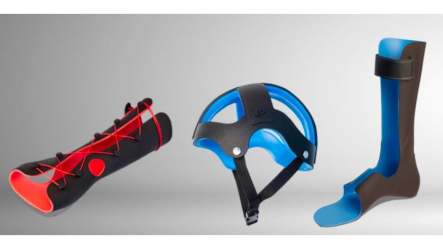
- Wave or Wiggle – As the name implies, a waveform infill pattern. Particularly useful when an object needs to be able to twist or compress. This is great to use for flexible materials.
- 3D Honeycomb Infill – One of the more popular infill patterns. Provides greater overall strength in all directions than a rectangular pattern, with very little increase in print time. It is generally considered the most commonly used, strongest infill pattern.
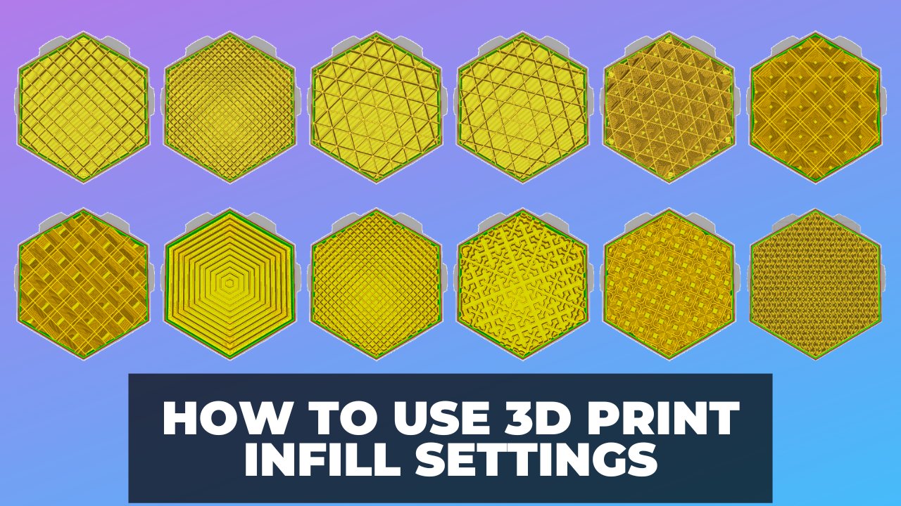
Here are some examples of Cura infill patterns. Some are novelty (like the cross, not pictured) and take longer, whereas others are faster. Honeycomb infill Cura is not currently available.
 Grid / Rectangular is a good default, fast option. Concentric is 2nd best to wave for flexible prints to keep it soft. Triangle is the strongest Cura infill pattern apart from Honeycomb.
Cubic is a great compromise between strength, print speed, and keeping the model light via low filament usage.
Cura Infill Overlap
Overlap is the amount the edges of your infill is printed into the outer walls of your print. If the overlap is too great, you’ll end up with the infill forcing through the walls – which isn’t a pretty sight.
The default is 10%, which gives room for good consistent adhesion between the infill and walls, without the infill coming through.
The default in most cases is sufficient, but should you want to change it:
Infill Overlap is hidden by default (as are most options in Cura 2.x/3.x)
To enable Cura Infill Overlap:
- Click on the little cogwheel next to infill when you mouse over it.
- Then check the box for infill overlap in the window that pops up.
- Default is 10% of LineWidth – i.e. 0.04mm for a 0.4mm nozzle.
Using Shell Thickness to Reduce Infill Percentage
The shell of an object consists of layers on the outside of an object. In many designs, the shell is often the first area that is printed in any layer. This means that shell thickness is intimately tied to infill amount and percentage.
When you increase the shell thickness of an object, you are also increasing its strength. This means that the object becomes sturdier and more capable of handling stress without the need for increasing the 3D printing infill density.
The majority of slicer programs will allow you to adjust the density of shell thickness in specific areas of the object, thereby offering localized strength where it is needed most.
Shell thickness is usually measured in print nozzle diameters. If you do decide to slightly increase shell thickness to reduce infill amounts, make sure that the thickness specified in your design is a multiple of your nozzle diameter.
This will help reduce voiding in your walls, bottom and top layers.
It really helps to use good quality filament when printing, especially if you’re looking to maximize strength while cutting back on material used. This is where high-quality filament comes into their own, your prints will be stronger, but with lower (or no) infill, you can use less material and save more time.
You may even save money with fewer failed prints or unusable parts.
It should be noted that there are some drawbacks to this approach. Any post-printing finishing process, such as sanding or annealing, will reduce shell thickness and directly affect strength.
This can be offset by increasing shell thickness even further. However, every increase in shell thickness will drive up print costs and time. So, at some point, increasing shell thickness to reduce or eliminate infill amounts becomes a losing proposition.
Experimenting with your designs and slicer settings will help you determine if this approach is right for your particular circumstances.
3D Printer Infill Percentage and Overall Object Strength
To understand infill, think about the doors in your home. Very few doors that are mass-produced are made of solid wood. The cost is simply too prohibitive. The majority of doors available commercially have a wooden or metal outside surface built around a core consisting of a lower density material.
This allows the door to be produced quickly in large volumes while remaining affordable.
So, to an FDM object. The typical FDM design consists of a solid outer surface (the shell) which is built around a lower density infill. As was the case with doors, this arrangement allows the object to be printed as quickly as possible at a reasonable cost.
The majority of slicer programs have a default infill setting somewhere between 18% and 20%. For many designs and objects, this default density is perfectly acceptable. However, when it comes to infill percentage, there is no hard and fast rule that fits all scenarios.
An 18% to 20% infill percentage may work fine for a prototype object where strength takes a backseat to form or shape. However, that same infill percentage will be completely inadequate for an object that has been designed to hold weight, like a bracket.
In general, the strength of an FDM object is directly tied to the infill percentage used during printing. For example, a part utilizing 50% infill is approximately 25% stronger than a part that utilizes 25% infill.
However, the amount of strength gained by increasing infill percentage does not increase linearly. For example, increasing infill percentage from 50% to 75% only results in an additional strength increase of 10%.
In addition to increasing overall object strength, infill percentage is also critical to object feature strength. For example, consider a two-piece object designed to connect together using an integral attachment feature like a snap-fit.
A snap-fit connector is usually designed as a cantilever. This means that its weakest point will be the small area attaching it to the main body of the object.
At a low infill percentage, the internal density of the cantilever is insufficient to withstand the stress of connection. As a result, it will snap off at its connecting point.
Increasing the infill percentage will increase the density of the connection, with a corresponding increase in strength.
The same situation holds true where a multi-part object is designed to be assembled using screws or bolts. Using a low percentage of infill usually will result in a weak connection, due to the fact that the bolt or screw is more likely to gain insufficient purchase or miss the infill altogether when density is low.
Again, if you’re looking to maximize strength, using a higher quality filament with a stronger pure based resin (higher grade and without filler that cheaper makes can use) with better layer to layer adhesion will build more strength into your prints.
Support Infill Percentage
Much the same way you may want to increase infill in areas that are higher stress, it’s often wise to reduce support infill percentage as much as you can get away with. For very small supports often 0% will be fine.
This allows you to save filament and keep printing speeds lean.
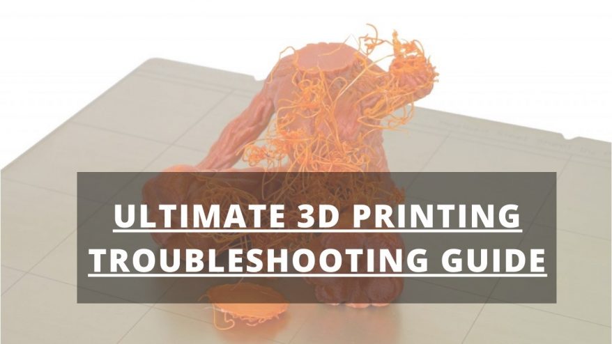
Infill Problems
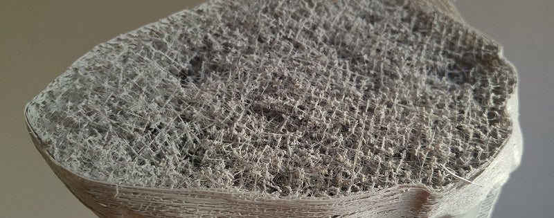
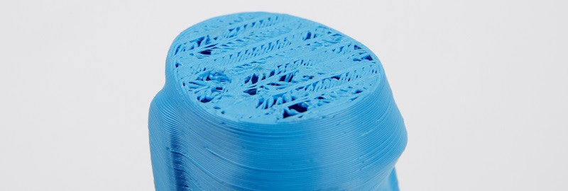
This common printing issue, shown in the image above, is often assumed to be a problem with your infill settings. However, this issue is actually a simple case of under extrusion – if a very extreme example.
Because the infill wall widths are often printed much thinner than the outer walls of your print, under extrusion issues nearly always become more obvious with infill, even if the thicker printed outer walls appear fine at first.
If you’re getting spongy infill problems, then you may need to look at sorting out your under extrusion issue first.
Other issues, such at the infill not touching or binding fully with the outer walls of your print (put simply, gaps between infill and outer walls), could be caused by incorrect slicer settings, if not already a symptom of under extrusion mentioned above.
To remedy this, you’ll want to ensure your ‘infill overlap’ settings in your slicer are set correctly. Often the cause is that they’re not set initially, or set to ‘0’.
Experiment with incrementally higher values (start at around 10% and usually don’t exceed 50%) with your specific print until the problem is solved.
Adaptive Makerbot Infill Patterns
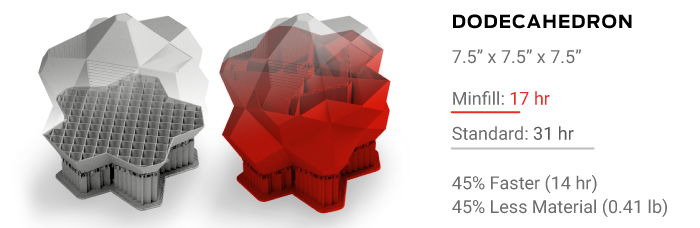
Makerbot has recently released a brand new infill pattern that they call MinFill. MinFill is short for ‘minimum fill’, and that’s exactly what this pattern does.
Using a newly developed algorithm, MinFill determines the minimum amount of interior support required for each section of a printed object.
According to Makerbot, MinFill automatically changes the infill settings depending on an object’s unique geometry. It also makes determinations regarding how much support is needed and where, eliminating user guesswork, testing and tinkering.
The end results are strong, beautiful prints that use less filament and print quicker than objects using traditional slicer infill settings.
Obviously, if you have designed an object that requires a specific amount of strength to function, you will still be required to manually set infill percentages.
However, for a large number of print jobs, MinFill could represent the wave of the future when it comes to determining proper infill percentage.
Summary
In the end, when thinking about infill, you want to remember the unique relationship between strength, cost and print time. Every increase in an object’s strength comes with a corresponding increase in printing cost and time.
The secret to a successful use of infill is to find the sweet spot where sufficient strength is obtained for an object’s designed purpose, with both cost and time being kept within acceptable parameters.