7 Key 3D Printing Slicer Settings You Need To Know
At 3DSourced we’ve covered everything 3D printing and 3D since 2017. Our team has interviewed the most innovative 3D printing experts, tested and reviewed more than 20 of the most popular 3D printers and 3D scanners to give our honest recommendations, and written more than 500 3D printing guides over the last 5 years.
3D printing isn’t just a case of hitting send from your slicer to your machine – the right slicer settings will greatly affect the outcome of your 3D prints.
In this article, we’ll explore six of the most common slicer settings that make all the difference in producing beautiful and useful 3D printed objects.
From layer height to print speed, we’ll cover what each setting does and how to adjust them to achieve the best results.
So whether you’re a seasoned 3D printing pro or just starting out, read on to learn how to get the most out of your slicer settings!
The Crucial Slicer Settings for 3D Prints
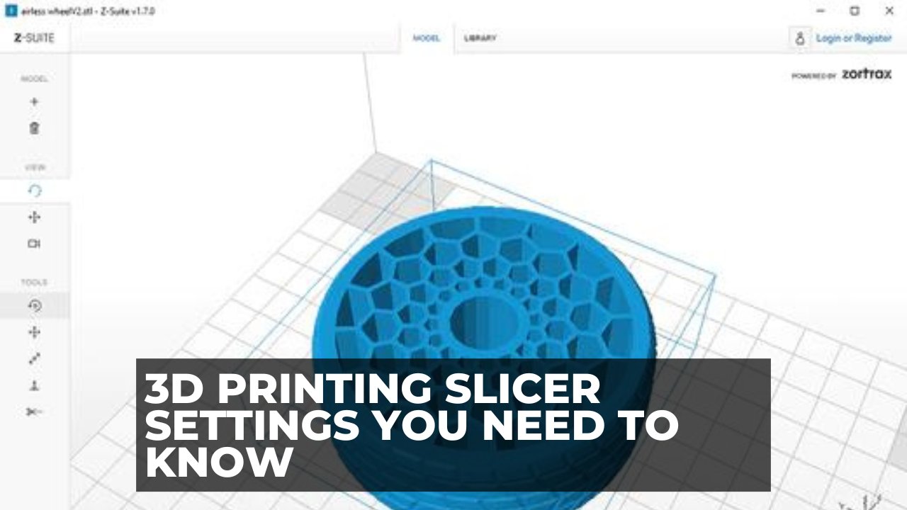
What is a Slicer?
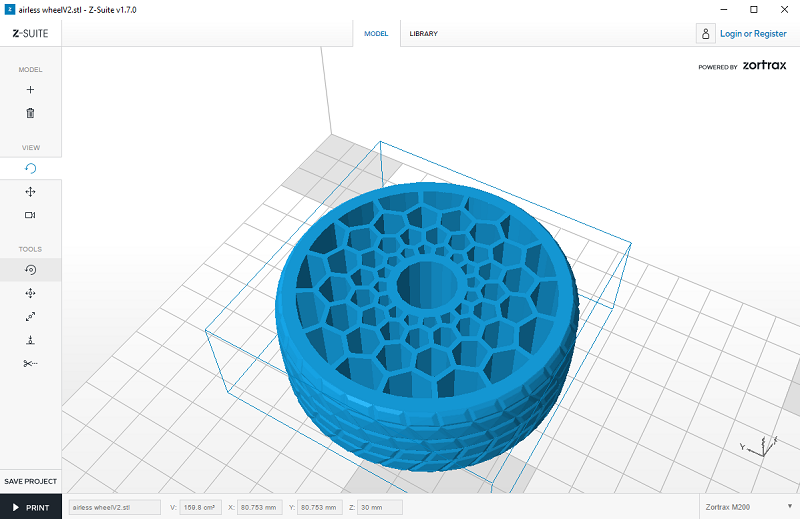
As you may know, a slicer is a piece of 3D printing software that takes a digitized 3D model and converts it into printing instructions that your printer can then use to turn the model into a physical object.
In essence, the slicer takes the CAD model and “cuts” it into layers. Think of a series of 2D pictures stacked on top of each other to create a 3D model.
It then calculates how much material needs to be used for that layer, where the material should go and how long it will take.
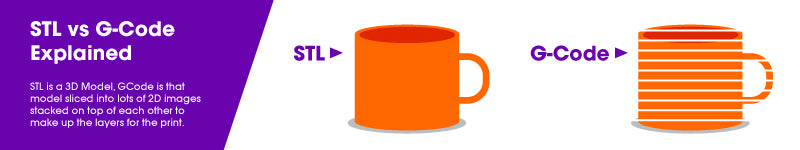
It then converts all of the information for each layer into one GCode file which is sent to your printer. You set up the job and, voila! Sometime later you have a physical representation of the 3D CAD model.
As you can see, the slicer plays an integral role in helping turn your 3D ideas into reality. Therefore, how you use the slicer, specifically how you use the settings, is often a critical difference between printing success and failure.
In this article, we’re going to look at 6 key slicer settings that are common to all the major slicer programs. We’ll tell you what they’re for and we’ll explain how to use them to increase your chances of producing beautiful and useful objects each and every time you print.
Best 3D Printer Slicer Settings

Layer Height
Layer height is the 3D slicer setting that establishes the height of each layer of filament in your print. In some sense, layer height in 3D printing is akin to resolution in photography or videography.
When you choose a thicker layer height, your object will have less fine detail and the layers will be more visible. When you choose a thinner layer height, a higher level of detail is possible and your layers will tend to blend into one another.
However, keep in mind that the thinner you make the layer height, the more time it will take to print the object in question, since there will be more layers to print.
An object with less detail, on the other hand, will print faster with a thicker layer height. It will also have a less smooth surface. Thicker layer height is often chosen for making a prototype of an object, since detailing and surface texture usually doesn’t matter.
Read more: best layer heights in 3D printing, and how layer height affects your results
Shell Thickness
A shell is the outer wall of a designed object. Shell thickness refers to the number of layers that the outer wall will have before infill printing will begin. The higher the setting is for shell thickness, the thicker the outer walls of your object will be.
Obviously, thicker walls make for a sturdier object, so if strength is a quality that you’re after, it pays to increase the shell thickness appropriately.
Obversely, delicate or decorative designs do not usually require strength. Increasing the shell thickness in these instances provides no real benefit and will likely distort the design of the object being printed.
Retraction
This setting is used to pull the filament slightly back into the print head during times when the head is traveling from one print point on an object to another.
This stops the filament from leaking out of the print nozzle and leaving strings of material across otherwise empty space.
If your CAD design has a discontinuous surface, your slicer program should automatically enable the retraction setting.
Fill Density
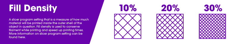
Fill density, or infill, is a measure of how much material will be printed inside the outer shell of the object in question. Fill density is usually measured as a percentage of the whole, as opposed to a unit of measure.
This means that if 100% fill density is selected, the printed object will be solid, with no empty space inside the outer shell. Likewise, if 0% is selected, the printed object will be empty inside. Fill density is used to conserve filament while printing and speed up printing times.
However, an object with more infill will be stronger and heavier than an object with less infill. Therefore, if either of these properties will benefit the printed object, consider increasing the fill density as needed.
Read more: optimum infill settings
Print Speed
Print speed is how fast the print head travels while extruding filament. Therefore, optimal speed depends on the object you are printing and the filament material that you are using to fabricate the object.
In general, simple objects with less detail can be printed faster without complication.
On the other hand, more complex objects with more detail will benefit from a slower print speed. Print speed can also affect adhesion to the print surface, cause under or over extrusion and other problems. Because of this, it pays to experiment with your print speed to see what works best for the job you’re printing.
Bottom/Top Thickness
This setting determines how much material will be laid down before the infill printing starts and how much material will be laid down after the infill printing is finished. The thickness of the material at the top and bottom of your object is important for two reasons.
First, thicker material at the bottom of your object will provide a stronger and more stable base. Second, thicker material at the top of your object will prevent sagging and pillowing from occurring when the top layer of material is laid down over the infill lattice.
This is especially important if you are using a smaller layer height setting. In such a case, the thinness of the layer can be insufficient to completely cover the infill unless multiple layers are used.
Setting the bottom/top thickness to be 6 to 8 times greater than the layer height ensures that there is enough material being laid down to adequately cover the infill without complications.
Spiralize – Smooth out the Z Scar
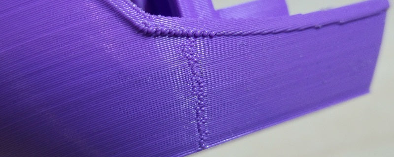
If you’ve printed an object and on one side there appears a vertical scar all the way up the print, this is called a Z scar (also known as a “zipper”). It’s formed from the printer starting and stopping each layer at this point.
This scar can be unsightly, and on very thin prints also significantly weaken the structure.
To remove the Z scar, you’re going to need to activate the Spiralize feature in your slicer. This makes the outer layers print in a continuous line all the way up the print, meaning there’s no definitive stop and start point and therefore no scar formed.
To activate Spiralize feature and remove the vertical scar:
In Cura, it’s called the “Spiralize outer contour” feature, in other slicers it may be slightly different. Make sure this option is checked when you convert your STL file to a Gcode.
It is useful to remember to only change one slicer setting at a time so that you can see the effect that the change is having on your print. If the change is beneficial, write down the change that was made and proceed, if necessary, to change another setting.
Changing multiple settings at the same time can cause chaotic conditions and a positive effect can be canceled out by one or more negative effects.
It may be useful when planning prints to know the length of filament on each size spool for various materials and sizes. To help with this, we’ve created this filament calculator.
Other articles you may be interested in: